
One part of the overall SmartLighting (SL) concept was the implementation of the second generation of SmartLighting technology, born at Anhalt University in the city of Dessau-Roßlau – the SLBasis project, funded in the program of Innovative Transportation systems of the European Union and the government of Saxony-Anhalt.
The SlBasis project is the next stage of the SmartLighting project development. This is a joint project of the Anhalt University of Applied Sciences and the city of Dessau-Roßlau.
Project goals. Development, installation, commissioning and optimization of energy-saving, motion-sensitive and adaptive street lighting system in Dessau-Roßlau. The SmartLighting technology from the Anhalt University of Applied Sciences is used and further developed for this purpose. In addition to energy saving, the application has the significant potential for optimization of traffic planning and management.
Project part – Dessau-Roßlau city. Procurement and installation of modern LED lights for streetlamps that can accommodate the SmartLighting modules and interact with them. Assembly and mounting the SmartLighting device boxes, communication units and sensors on the streetlamps, procurement and installation of information boards, maintainance of the lamps. Gathering the operation data including traffic activities for the optimization of traffic flows.
Project part – Anhalt University of Applied Sciences. Development of SmartLighting devices for mounting on lamp posts, development of the control logic as well as a web-based lamp monitoring system and the data transfer protocol, development of software for collecting, evaluating and displaying statistics on traffic, testing, evaluating and optimizing the system. Integration of the reception boards and displaying the traffic information.
SmartLighting – Energy-saving Intelligent Street Lighting System
To optimize the energy usage and to support people with well illuminated streets at night in rural areas, the SmartLighting concept has been developed at Anhalt University of Applied Sciences. The goal of the project is to create a large-scale wireless sensor network over the existing street lighting infrastructure in order to establish a SmartLighting system. In this system the maximum amount of power will be used only at the spots, at which it is needed and only when it is needed. The system fully relies on pedestrians traffic, calculates and provides necessary lighting zones depending on their movement direction, while the street areas without any movements remaining unlighted. This leads to a decrease of overall street lamps’ working time, saving a huge amount of energy and prolonging the lamps life cycle.
The main idea of the SmartLighting project is to develop an intelligent system for street lighting, which would significantly decrease the power consumed by lamps while successfully performing the main purpose of such systems – to illuminate roads, paths, open and closed spaces providing the safety and comfort during dark time of day to people.
The system can be represented as a set of streetlights with special devices attached to them. Each device has a number of necessary modules, such as motion sensors, like IR or ultrasound sensors, lamps and communication appliances for the cooperation with neighboring nodes. Therefore, each node of the system operates autonomously and independently with a purpose to send messages about some activity or inactivity (e.g., a man is moving to some direction) to the other cooperating nodes.
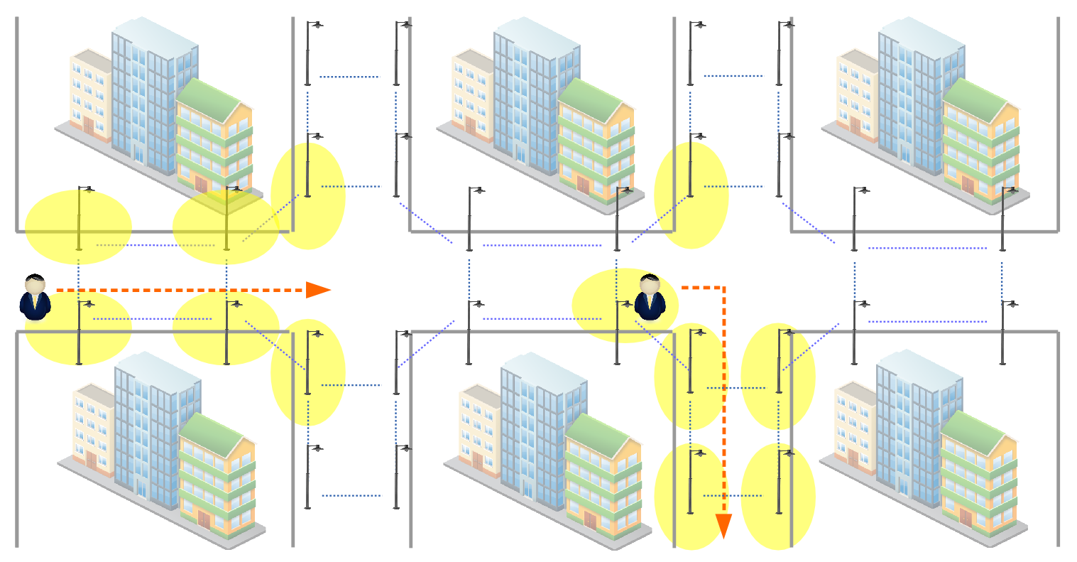
Figure 1. The SmartLighting concept
The communication among the nodes is assumed to take place either in wireless (e.g., 802.11, 802.15.4 standards) or wired (using PLC technology) environment. A number of such nodes can be considered as an ad-hoc network with a static topology whose main objective is to share the information between each other quickly and reliably. So, the underlying data network comprises a basis which provides a correct functionality of the SmartLighting system.
Application side
An example of possible application scenario is shown in Figure 1. The proposed lighting system is deployed on some part of a town as a number of streetlights with attached controller devices, covering the streets. During the dark time of day when artificial lighting is needed, pedestrians are walking along the street in a chosen direction. One of the system’s nodes detects the pedestrian with an aid of IR or ultrasound motion sensors. At this instant, the node gives a signal to switch on the light in the corresponding lighting mast and sends a message to its neighbors containing the information about the occurred event (a pedestrian has appeared or disappeared, its velocity, direction, location etc.). After receiving the message from the originating node, the neighboring nodes know the information about the event and, based on it, they can determine their further actions – either switch on the light (when the pedestrian is approaching) or switch off (when he is moving away) and send an updated information to the other nodes. In this way, the pedestrian’s path is being constantly illuminated until he leaves the coverage area of the system. Thus, the system provides comfortable illumination for people along their path while saving a substantial amount of energy during their absence.
The application continuously gets information from the external environment via set of sensors, as well as efficiently performs inter-communication between every other nodes in the network for the purposes of auto-configuration, service and data information exchange.
From the logical perspective, the application provides the following functions:
- detection of a pedestrian’s movement direction (vector detection
- lighting zone detection
Those functions are described below. Also, 2 miscellaneous features, related to the application domain – auto-configuration and inter-node communication routine – are described in Section 3 and 4, correspondingly.
Vector detection mechanism. The key idea behind that – is to use sensors and nodes interconnectivity to predict a movement direction (or, a vector) of a detected object (pedestrian, car, etc.). The system writes timestamps of the occurred events, and, based on the expected arrival time interval of an object – the neighboring nodes make decisions to switch on the lighting zone along the vector (Figure 2).
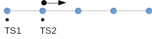
Figure 2. Movement vector detection
Lighting zone detection. The lighting zone detection algorithm focuses on effective message delivery through the lamppost network, based on the previously calculated movement vector.
Given the input parameters: movement vector and number of lamps to be switched on in forward (F), backward (B), left (L), right (R) directions – the system forms a tuple (<vector, F, B, L, R>) and broadcasts it further to the neighboring nodes. The neighbors receive the message, and, depending on their position in the network, forward the message further, or discard it (Figure 3). In that way, the appropriate illumination zone along the movement direction is provided.
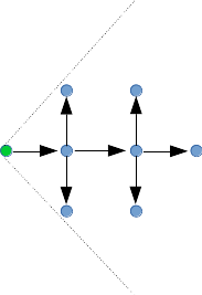
Figure 3. Vector message distribution over the network
Autoconfiguration feature. In the SmartLighting project, the auto-configuration feature can be divided into 2 main parts:
- automatic IPv6 address configuration scheme
- geographical position detection scheme
One of the key issues essential for the system’s implementation, is an auto-configuration problem and location discovery mechanism, in particular. It is obvious, that in order to function properly, the system has to know the exact location of all communication nodes and lighting masts around it at any instant. Those 2 main objectives are explained in detail next.
Addressing scheme. For the purposes of inter-network communication, IPv6 addressing scheme is used with special header formatting, which includes the information about the node’s current state and the nearby environment. The last bytes of the 16-byte IPv6 address field are used for location discovery purposes [1] (for example, to insert an explicit information about the location of the node, such as – geographical coordinates, number of the nearest road or building, etc.), as it is shown on Figure 4.
Figure 4. Addressing scheme for the network
Detection of a node’s geographical location. It is obvious that, in order to perform such intellectual street illumination, each node should explicitly know its geographical position in the network. This task can be solved in a couple of the proposed ways:
- each node is equipped with GPS receiver,
- set the coordinates using an external GPS device,
- apply sophisticated algorithms which will use available information from the physical environment (RSSI, packet delay, number of hops).
The first solution is quite trivial, although it will significantly increase a total cost of the device and the end-system, and, moreover, the GPS receiver will remain unused most of the time, since all the nodes are static. The second variant is flexible, easy to implement and it will not cause significant additional costs. The third variant is non-trivial and involves some research work, currently being conducted at our lab.
Communication side
An inter-communication functionality plays a very important role in this project, since all the messages (service and application data messages) have to be efficiently routed and delivered to a given destination node, considering wireless or wired transmission medium.
In terms of the project, there have been developed a routing protocol based on the improved concept of DSR (Dynamic Source Routing), which showed better performance in terms of average one-way delay, data throughput as well as PLR (packet loss rate). The concept of DSR routing is shown on Figure 5.
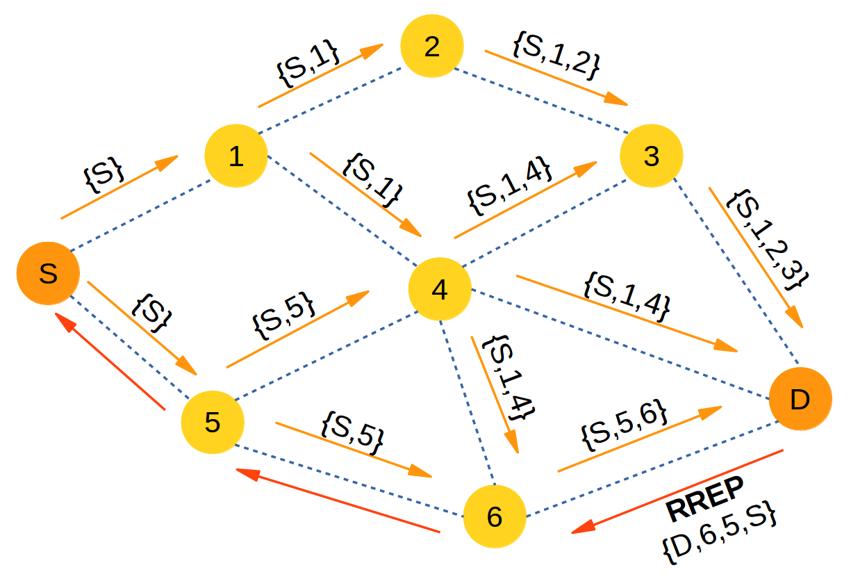
Figure 5. DSR route request broadcast
As for underlying link-layer communication protocol, two possible approaches are being considered – wireless (802.11 wi-fi in ad-hoc mode and 802.15.4 low-energy standard) and wired (Power-Line Communication – PLC), with a priority given to the wireless approach.
Wireless approach – 802.11 and 802.15.4. With this approach, each SmartLighting node (a communication device) will be equipped with wireless 802.11 or 802.15.4 adapter. All upper-layer communication routine will be managed by the node with the developed routing protocol.
A big advantage of this solution lies in uniformity of the wireless transmission medium, where all the communication is made through wireless adapters. This makes this solution viable in every possible location or conditions.
Wired approach – Power Line Communications (PLC). The PLC technology, at least in theory, could bring better performance comparing to the WiFi solution. However, there is one issue which makes this approach less possible to apply. PLC relies on the existing power line infrastructure and its performance varies significantly depending on the physical parameters of the wires, number of power transformers and so on. Therefore, in order to install the system based on PLC, there should be done additional research on the matter of underlying power line infrastructure, used at the given lampposts.
Hardware side and requirements
The hardware should contain a set of motion detection sensors, communication interfaces (PLC, 802.11 or 802.15.4), Linux-based SoC controller, power lamp controller.
For a testing purpose, there have been developed a Smartlighting system prototype (Figure 6). The prototype testbed consists of 20 custom designed small lamps, with a controller for the sensor and the lamp, attached to it. It includes several communication appliances: WLAN module, 802.15.4 radio module, power line communication module, as well as motion sensors: PIR, ultrasonic. The core component of the controller here is the ARM based single board computer. All other components are connected to the SBC. This board is operated by Linux operating system which runs the developed applications. A Beaglebone SoC [2] is used for this purpose, representing quite powerful, easy to enhance and well documented platform for development purposes.
Test installation in Bernburg-Strenzfeld
A network of 19 SmartLighting subsystems using PIR sensors and Wifi components was installed in late 2017 along a road in Bernburg-Strenzfeld. The installation supplies light to cyclists along a road connecting Bernburg-Strenzfeld with its Hochschule Anhalt Campus and the main urban area of the city of Bernburg. Two of the subsystems have internet connection by mobile phone.
The SmartLighting networks enables a string of off-grid lights with photovoltaic panels and batteries to supply sufficient light by savings of more than 90% of the otherwise necessary electrical power. SmartLighting’s computing capabilities were also used to monitor the status of the batteries and power generaiton, which helped to get the installation running during the winter time with minial light hours and frequent overcast conditions. An offgrid solution wihtout SmartLighitng would have required vastly bigger and thus more expensive photovoltaic panels and batteries.
The regional television station MDR televised a report about the SmartLighting installation in Bernburg Strenzfeld.
Project manager – Eduard Simens